24 Volt Low Voltage Transformer Reads 28 V
 Troubleshoot Low Voltage Transformers for Heating & Air-conditioning Systems
- POST a QUESTION or Annotate about wiring & testing low voltage transformers for HVAC equipment like air conditioners or heaters & in low voltage wiring systems
InspectAPedia tolerates no conflicts of interest. We have no relationship with advertisers, products, or services discussed at this website.
Low voltage (12-24 VAC) transformers diagnostic, installation & repair guide for HVAC & lighting systems:
This article explains how low-voltage transformers are used on heating, rut pumps, & air workout systems to provide power for thermostats, zone valves, and other relays and controls.
We explain how a depression voltage transformer is installed and wired, where the device is unremarkably located, and how to test or troubleshoot & repair low voltage transformers using a VOM or DMM.
We also provide an ARTICLE INDEX for this topic, or you can try the page top or lesser SEARCH BOX equally a quick way to find information yous need.
How to Troubleshoot Low Voltage Transformers for Heating & Air-conditioning Thermostats
 Question: How exercise you lot tell if a transformer is bad? How do you test a low voltage transformer?
How do i tell if a transformer for thermostat is bad ?- Erwin five/12/12
How practice you examination a low voltage transformer? - Den 7/16/12
Answer: how to examination a depression voltage transformer for heating or ac
Erwin if you disconnect the depression voltage wires continued to the transformer terminals and employ a VOM you should discover voltage, usually 14V. If the device looks burned, hot, or smells, don't even bother testing. If information technology has been buzzing that'southward another clue.
Den,
Remove all of the the low voltage wires from the two (or more) screws on the height of the transformer. Usually you lot'll run across a small-scale gauge red and white wire merely continued under two screws on the upper surface of the transformer itself.
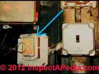
Some heating transformers for thermostats that utilize more than 2 wires will have more than two screws and more than than ii low voltage wires continued or there may even exist multiple sets of thermostat wires connected if the transformer is powering more than i room thermostat. (photograph above left).
Check for output voltage: with power to the transformer "on", using the VOM on a low voltage scale (say 0-24VAC ) check for voltage between the 2 screw terminals.
If the transformer itself is receiving 120V power but at that place is no voltage between the 2 low voltage output screws, then it is not working.
To test for a bad low voltage transformer you but need a volt-ohm meter or a digital VOM.
Run across DMMs VOMs SAFE USE OF for communication on how to use a volt-ohm meter,
and
see TEST EQUIPMENT, Electric GUIDE for advice on how to electrical test equipment safely. And of course y'all'll have to exist sure you have plant and are testing the correct low voltage relay, as we will explain in the details below.
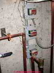
In our photograph you can come across a low voltage transformer mounted onto a iv-inch electrical box that is in turn secured to (and powered from) a gray-covered electrical panel. Just every bit in that location are four circulator pumps shown in the photograph, y'all can figure at that place will exist more LV transformers and more circulator relay switches nearby, connected to other room thermostats in this building.
Why? A typical residential-grade low voltage transformer cannot handle the full electric current draw (in Amps) to back up multiple circulator pump relays or other controls.
Variation in Output Voltage from Low Voltage Transformers
Reader Question: 11/24/2014 john said:
Shouldn't a 24v transformer put out 24V? I'm trying to install a nest thermostat but just getting 18V (apparently it needs at to the lowest degree 20) from a brand new transformer.
Reply:
John,
Depression voltage transformers catechumen 50Hz or 60Hz (cycle) line voltage (120 to 240V) AC (alternating current) to depression voltage typically 12, 18, or 24 volts Air conditioning at a high frequency Hz, possibly every bit high as twenty to 50KHZ, that'southward xx,000 to l,000 Hz.
There are other common low voltage output levels, for example 5-6V Air conditioning on many device chargers and there are besides voltage converters that may produce DC rather than Ac electric current.
What that means to yous is that earlier replacing your maybe lacking low voltage transformer there are some things to check:
- Check the equipment low voltage requirement specifications
on your HVAC system or low voltage lighting or other depression voltage equipment controls to see what voltage is required. Also confirm that yous are using the proper type of low voltage transformer or ability adapter. For example, if the equipment being powered requires 5VDC don't employ a low voltage transformer or power supply providing AC.
- Look at markings on the low voltage transformer itself to see its output rating. Yours might be an 18V unit of measurement.
- Bank check the ability connections to the low voltage transformer:
Bank check that the input wires (unremarkably heavier approximate wires) to the transformer are properly continued to the line voltage supply (typically 120V or 240V in most buildings). Check that the output or low voltage terminals on the low voltage transformer are connected to the low voltage wiring.
- Measure the output voltage at the low voltage transformer (using a VOM or DMM) after removing the low voltage wiring that was connected to it - thus eliminating any effects of the wiring itself. Most HVAC thermostats and controls operate at 24VAC. Low voltage lighting systems typically operate at 12V or 24V only other equipment or systems may require dissimilar voltage levels.
Annotation: For a typical magnetic LV transformer used on HVAC systems a typical DMM or VOM will work adequately. But Pegasuslighting.com warns: "Since most voltmeters give misleading readings when applied to high frequency currents the voltage on an electronic low voltage transformer can be measured merely by using a "true RMS" voltmeter with a sufficient range."
- Determine the type of low voltage transformer you lot are using:
electronic low voltage transformers may not behave identically to magnetic low voltage transformers.
For a typical eighteen-24V transformer used on HVAC equipment, the LV transformer is a traditional magnetic type.
But if you are using an electronic low voltage transformer instead of a traditional magnetic low voltage transformer, the loftier frequency but low voltage produced by the transformer tin can leave the circuit vulnerable to a more significant voltage drop that occurs on the lower-frequency higher voltage wiring in the edifice.
- Check the low voltage wiring:
With the low voltage wires asunder from both the depression voltage transformer and from their control-end, check the wires for shorts or breaks. Also note that if you are using very pocket-size guess wires or a very long wiring run, depending on the power (watts) load on the circuit there could be a voltage drop.
Pegasus lighting (pegasuslighting.com) points out that "in that location tin can be a substantial voltage drop if the wires carrying the high-frequency current are long, thin, or far autonomously."
- Cheque the line voltage levelto be sure information technology's inside specifications at the source of ability to the low voltage transformer, typically 120V in residential buildings.
How your low voltage thermostat and its low voltage transformer work & how they are wired
It's usually pretty simple to sympathise the wiring and office of a depression voltage relay on HVAC/R equipment.
The low voltage transformer changes (transforms) house current (at 120V Ac) to a lower voltage (usually around 14V to 24V Ac) used to operate the room thermostats and mayhap other heating or air-conditioning controls.
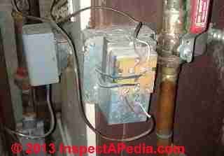
The low-voltage transformer shown at left, a reader-contributed photo, is feeding two pairs of low voltage 24V circuit wires (cherry-red and white); the 120V power wires feeding the transformer are the heavier wires in the eye of this device. Click to enlarge this or whatsoever paradigm.
So the transformer has 12V wires connected to its input terminals (not visible in our photo at left as past code the 120V wires accept to be within of that 4" metal electrical box). The low voltage thermostat wires that bring operating electric current (xiv-12V VAC) to the thermostats are on the exposed surface of the transformer.
In the simplest applications, two wires, typically red and white, are connected at the transformer.
A "C" or common concluding wire on the low voltage transformer is connected to the command relay that operates the heater or air conditioner, and
an "R" terminal on the transformer is connected starting time to the thermostat (which acts as an "on-off" switch) and from the thermostat onwards to a thermostat terminal found on the heater or air conditioner's chief control or circuit board.
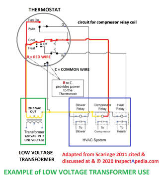 In HVAC installations such every bit air conditioners, oestrus pumps, and heating systems, y'all'll observe that a red wire is used to connect between the R or LOAD last at thelow-voltage transformer and the R terminal at the thermostat.
HVAC system Transformers: Details near thermostat wiring and low voltage control wiring for tranformers used on heating and air conditioning circuits are plant
at THERMOSTAT WIRE CONNECTIONS.
Low Voltage Lighting / Receptacle Switching Organization Transformers: Details about thermostat wiring and depression voltage control wiring for tranformers used in low voltage lighting control systems are
at
Reader Question: how many devices can a standard 24VAC transformer back up?
2016/03/16 Peader said:
I have a 40 year one-time house that has been remodeled over the years with additional multiple heating zones, modernized thermostats with wireless computer access, intercom, etc. My 24vac control transformer has started buzzing very loudly and I programme on replacing it.
With this new need on the 24vac side should I consider increasing the existing transformer capacity of 40VA to something larger? Is at that place a way to determine the output capacity of the transformer?
Reply:
Thank you for the question Peader.
For other readers, 'VA' stands for Volts x Amps. Volts multiplied by Amps is also the classic definition of a Watt. If you claw up more than devices drawing more than electric current than a transformer can provide, it'll burn down up - fail.
As well to be clear for other readers, the OUTPUT VOLTAGE of a replacement transformer should non be changed - that is if y'all are running 24VAC devices y'all want 24VAC supplied by the transformer. You wouldn't change to a 12VAC transformer (for instance).
Hither is a typical 24VAC transformer product specification using Robertshaw data every bit an case:
Course 2 Transformer, 40 VA Rating, Input Voltage 120VAC, Output Voltage 24VAC, Multi Mounting, Protective Device Fuse, Primary Connection 8 In. Leads, Secondary Connection eight In. Leads, 1 Stage, l/lx Hz, Not Rated Temp. Rise, Open Enclosure Type, Enclosure Rating NEMA one, Enclosure Finish Bare Steel, Height ii.75 In., Depth 3.25 In., Width 2.44 In., Standards UL 1585 File Number E110657, E92807, E99697, CSA File Number LR107325-1, NEMA
A 24VAC transformer rated for 40VA (volt-amps) means that information technology can support 40 / 24 = i.6A or 1.6 amps of current depict (load). That is its output capacity and the reply to your question.
Add together upward the current requirements (amps) of the devices y'all want to support. E.g. one zone valve might want 0.three Amps. so the most you'd put onto one 40VA transformer would be 4 such zone valves - though I've seen a few working installations at which five or even six zone valves on a single transformer.
The VA rating of the transformer should be greater than the load of all the devices connected to it.
So how did they get away with wiring so many zone valves onto one transformer? Luck. Usually not all of the zone valves are existence turned "on" by their respective thermostats at the same moment.
During activation the zone valve motor runs for less than a minute.
Only somewhen, on a very cold night, and with bad luck, all five or half-dozen thermostats try to turn on all five or half-dozen zone valves at the same time. Maybe the homeowners came back to a cold firm and ran amok turning up all of the thermostats in the course of a infinitesimal. Hiss. Fizz. Dead transformer.
Typically an older wiser, HVAC installer adds boosted transformers rather than installing one giant one serving everything in the house.
That can also avert having to ophidian long runs of low voltage wire - depending on where your various devices are. For case an installer hooking up 6 zone valves would install two 24VAC 40VA transformers and wire iii zone valves to each.
I'd guess that your wireless computer access is talking to a wireless router that is plugged into a 120VAC wall receptacle so that ought not be a business.
I've hooked up three NEST thermostats in a test building, all working just fine off of the original transformer that originally supported the onetime Honeywell round units.
Run across NEST LEARNING THERMOSTATS - the manufacturer probably took intendance to be sure that their new production would work in older homes without requiring homeowners to change out their thermostat transformer or add additional ones.
Normally an intercom system has its own split up transformer every bit does a traditional home doorbell and equally does the receiver for a remote operated garage door operator.
Testing the Low Voltage Heating or Air Conditioner Transformer
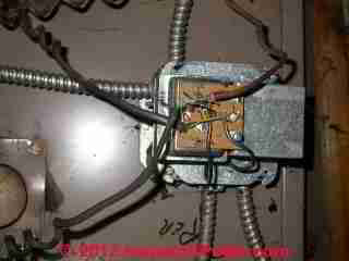
When we think that there may be a problem with getting power to a thermostat (if it needs power) or to other low-voltage-operated controls in an HVAC arrangement, the "test" of the depression voltage HVAC transformer involves these very simple steps:
- Find the low voltage transformer
that is operating the thermostat or other control device. Ordinarily the transformer is visible, mounted on an electrical box in the utility area where the heater or air conditioner blower unit is installed (blue arrow in our photo, above left), may be mounted within of the furnace or air handler itself (photo at left).
On some modern HVAC equipment the low voltage transformer may exist harder to spot as it may be incorporated into a more complex circuit lath or component.
In all cases, yet, if y'all follow the small gauge low-voltage wires from your thermostat dorsum into the furnace or air handler chiffonier you can find wires of this aforementioned dimension connected to a transformer.
- Check that all of the wires and connections
are in fact intact, un-damaged, and properly continued. If you suspect that a thermostat wire has been damaged between the transformer and the thermostat, y'all can try a uncomplicated continuity test - disconnect the thermostat wires and connect them together at one end of the run - then exam for continuity between the wires using a VOM at the other, asunder end of the pair.
- Cheque that the low voltage transformer is is providing ability
using a VOM we test for voltage between 12-24V AC at the transformer's output screws. Here are the procedural details for testing a depression voltage transformer for live output power:
Remove all of the the low voltage wires
from the 2 (or more) screws on the superlative of the transformer. Usually you'll see a small estimate ruby and white wire simply continued under 2 screws on the upper surface of the transformer itself.
Some heating transformers for thermostats that utilise more than two wires volition have more than two screws and more than two low voltage wires connected or there may fifty-fifty exist multiple sets of thermostat wires connected if the transformer is powering more than one room thermostat. (photograph higher up left).
Check for output voltage with power to the transformer "on", using the VOM on a depression voltage scale (say 0-24VAC ) check for voltage betwixt the 2 screw terminals. If the transformer itself is receiving 120V power but there is no voltage between the two low voltage output screws, then it is not working.
- Listen for buzzing
Too before a low voltage transformer fails yous may hear it buzzing - a condition that tin continue for some fourth dimension merely ultimately is probable to atomic number 82 to failure.
- Inspect for overheating or burn upward Finally, by visual inspection you MIGHT see fire marks or evidence of overheating - but I wouldn't depend on visual inspection alone.
Reader Comment: Buzzing low voltage transformer
(Mar 3, 2015) Raymond Rackley said:
Thank you for this website.I learned and then much about what I have been trying to say to every electrician that has come up to solve the problem of buzzing/vibrating transformers. They all say information technology's normal but when information technology keeps waking you upwards when the thermostat calls for oestrus in the middle of the night, information technology is far from normal.
You have taught me to stick to my guns and hire someone who will listen and sympathize that I have already found and isolated the problem.
Now I just need them to either replace the transformer or check the thermostat that just clicks at will. Thank yous for breaking things down in English to a novice in heating and electricity.
Now I demand a service technician.
List of Low Voltage Transformers Establish on HVAC/R Equipment and in Other Building Applications
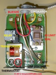
Watch out: there may be more than one depression voltage thermostat, for example 1 controlling heating and some other controlling ac in your edifice.
Or in that location may exist additional depression-voltage thermostats providing ability to private hydronic heating zone circulator pump relays and to the thermostats that control each of those zones (see our photo at the superlative of this folio).
Lookout out : in that location are other low voltage transformers institute on air conditioners, boilers, furnaces, circulator relays, fan relays, etc. that are non the units providing low voltage to the room thermostat and main on-off HVAC/R controls.
- Primary control LV transformer: The low voltage transformer found inside of a heating banality primary command and used to operate circulator or other relays (transformer visible at lower left in our photograph at left). The low voltage transformer shown in the lower left in this photo of a primary control is not the thermostat power supply.
Other chief controls used on hydronic heating systems and boilers may accept two of these relays, ane for the oil burner circuit and one for a circulator pump.
In our photograph y'all can indeed see two thermostat control wires connected to the ii screws marked "T" just below the LV relay. Those thermostat wires are carrying the "on-off" signal from the room thermostat.
The relay itself operates a 120V relay found but to a higher place the LV transformer (center left on the control board) that is used to switch the heating boiler oil burner on or off.
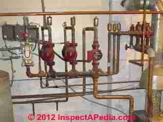
- Low voltage transformer operating 1 or more hot h2o heating circulator relays.
The transformer in the principal control of virtually heating boilers as well operates one circulator pump.Only in a building with multiple hydronic heating zones that utilize individual circulator pumps, each additional circulator pump, presumably serving an individual heating zone, volition be turned on or off by the room thermostat located in the zone the circulator pump serves. (meet our photo at the summit of this folio).
In our photo at left, you tin see at middle three red circulator pumps (ii different models have been installed). At the upper left corner of the photograph in those greyness Honeywell labeled control boxes are private circulator pump relay controls, each of which will be activated by an individual thermostat.
Nosotros tin can run across that nosotros take a gas fired hydronic heating system boiler with three zones, merely we don't know from the photo if all three are heating zones - one of those relays and circulators could exist supplying estrus to an indirect fired h2o heater.
See Circulator Pumps & Relays and
besides INDIRECT FIRED H2o HEATERS for details.
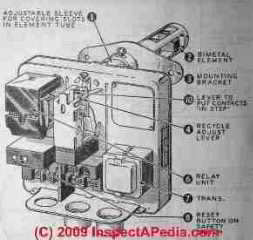
- Cad Jail cell Relays Low voltage transformer operating the oil burner circuit within of a cad cell relay. Details are
at CAD Cell RELAY SWITCH.
- Doorbells
Run across DOORBELL troubleshooting
- Draft Inducer Fans Low voltage transformer operating the control for a draft inducer fan found on flue vents on some heating equipment.
Come across Typhoon INDUCER FANS
- Stack Relays Low voltage transformer in a stack relay or protectorelay that operates an oil burner - schematic at left. This command is detailed
at STACK RELAY SWITCH
- AUTOMATIC VENT DAMPERS On heating equipment
- LOW VOLTAGE BUILDING WIRING that controls lights, electrical receptacles
- ZONE DAMPERS in forced warm air or cooling systems
- ZONE VALVES, HEATING On multiple zone hot water or hydronic heating systems
- Many other relays, solenoids, and devices that operate equipment found in buildings
Reader Comments & Q&A
Vic
I'll be glad to aid but we kickoff need to become an accurate understanding of the situation.
If you had a separate oil-fired water heater with its own oil burner and controls, there would be no connection whatsoever to a home heating furnace (forced warm air heating system).
If your home heating system was a hot water boiler (and radiators or baseboards) that was also heating an indirect-fired hot water tank and that is what you abandoned, so indeed a thermostat at the hot water tank would have called for a circulator to run to re-rut the tank with hot water from the heating boiler. It would accept appeared equally a separate heating zone equally far as the domicile heating boiler was concerned.
Search InspectApedia.com for INDIRECT Water HEATER to read details of how those heaters are hooked upwards and operated.
Assuming you meant home heating boiler (and used the give-and-take "furnace" generically), you'd remove all wires and controls that previously connected the heating boiler to the indirect fired h2o tank.
And so review the aquastat settings on your heating boiler and the thermostats in your home.
Or run across these two diagnostic articles
NO Oestrus BOILER - for hydronic (hot water) heating systems - https://inspectapedia.com//oestrus/Heating-Boiler-Diagnosis.php
NO Rut FURNACE - for forced air heating systems - https://inspectapedia.com/rut/Furnace-Diagnosis-Repair.php
Hello, We replaced a oil hot water heater with an electrical tank. Indecommissioning the tank to remove it, I capped/plugged the chimney/stack pipage at the 'Y', capped the oil line 'T' fitting with a flare nut and disconnected the 120V cable to the tank. The problem I am up against is the 2 wire depression voltage line that goes from the oil furnace to the tank.
When I disconnect it at the h2o heater the furnace won't run. How do I terminate that low voltage line ?
Sorry Gene, I have this trouble too - sometimes I forget where I posted a question.
Your original question was posted at the bottom of ZONE VALVE WIRING
By luck I spent a sickening amount of time working on adding information and illustrations to your question and my reply this night.
You tin can observe all of that information repeated and possibly expanded a bit ALSO at this FAQs page:
ZONE VALVE WIRING FAQs
What I practice is use the InspectApedia on-page search box to endeavour a search for words I can retrieve from a question or comment. Google will (below some ads) return the most-likely or best matches and one of those is usually the article I desire.
You can too click the piddling "email me replies" button under Comments Box though I've not used that and am not sure how well it works.
How can I go dorsum to my question from yesterday
Some of my low voltage lights are on and will not turn off and some of them are off and won't turn on. I institute the transformer and information technology is hot, hot, hot to the touch on. Any idea what is causing all this?
Sergio
I may have misunderstood merely with power disconnected from a 24VAC transformer I would not await to read any voltage whatsoever. Perchance your meter is out of aligning.
I tested a 24 volt transformer with the ability off and information technology gave me .7 volts is it good or should it give me more volts?
...
Go on reading at Low VOLTAGE TRANSFORMER, TRANSVERTER DIAGNOSIS or select a topic from the closely-related articles below, or see the consummate Article INDEX.
Or encounter LOW VOLTAGE TRANSFORMER FAQs - questions & answers posted originally at this page
Or see these
Low Voltage Wiring Manufactures
- BUZZING Dissonance DIAGNOSIS - topic abode
- BOILER CONTROLS & SWITCHES
- FURNACE CONTROLS & SWITCHES
- HEAT WON'T TURN OFF
- HEAT WON'T TURN ON
- HUMMING NOISES in BUILDINGS - topic home
- LOW VOLTAGE BUILDING WIRING - dwelling house
- Common WIRE at THERMOSTATS
- Depression VOLTAGE WIRING Organization COMPONENTS
- Low VOLTAGE LIGHTING & Control RELAYS
- LOW VOLTAGE TRANSFORMERS, TRANSVERTERS, CONVERTERS
- LOW VOLTAGE TRANSFORMER, TRANSVERTER DIAGNOSIS
- LOW VOLTAGE TRANSFORMER TEST
- Low VOLTAGE TRANSFORMER WIRING GUIDE
- LOW VOLTAGE WIRING REPAIR or UPGRADE
- Depression VOLTAGE WIRING REPAIR PARTS SOURCES
- THERMOSTAT WIRE CONNECTIONS
- THERMOSTAT WON'T TURN OFF
- THERMOSTAT WON'T TURN ON
- VOLTS MEASUREMENT METHODS
Suggested commendation for this web page
Depression VOLTAGE TRANSFORMER TEST at AuditApedia.com - online encyclopedia of building & environmental inspection, testing, diagnosis, repair, & problem prevention advice.
Or see this
Alphabetize to RELATED Articles: Article Index to Electric INSPECTION & TESTING
Or use the SEARCH BOX found below to Inquire a Question or Search InspectApedia
...
Ask a Question or Search InspectApedia
Try the search box just below, or if yous adopt, post a question or comment in the Comments box below and we volition respond promptly.
Search the InspectApedia website
Note: appearance of your Comment beneath may exist delayed: if your comment contains an image, web link, or text that looks to the software as if it might exist a web link, your posting will announced after information technology has been approved by a moderator. Apologies for the delay.
Technical Reviewers & References
Click to Show or Hide Citations & References
Publisher InspectApedia.com - Daniel Friedman
cravenmosencestiss.blogspot.com
Source: https://inspectapedia.com/heat/Low-Voltage-Transformer-Test.php
0 Response to "24 Volt Low Voltage Transformer Reads 28 V"
Post a Comment